The Rotary Engine (august 2003)
About my ideas:
Most of my ideas are things that seemed like a good idea, or a novelty when I thought of them
only to find out when I tell people about it, that somebody had the same idea long before me.
I'm not a very well read person, I'd much rather create than research. I'd rather write my own
music than play somebody else's. And I'd rather reinvent the wheel than buy a prebuilt wheel.
This may seem wasteful since the wheel has been perfected over thousands of years, but
I'm probably better at building wheels now than your average American.
My idea for a Rotary Engine:
Not to poop on Mr. Wankel, but I have a hard time agreeing with the statement that
the Wankel rotary engine is really a rotary engine. To me it looks more like the spirograph I used
to play with when I was a kid.
A turbine is rotary. It spins. It's balanced, it doesn't wobble.
A Wankel engine, while certainly a marvel of engineering and solutions to sealing problems,
doesn't seem to me to solve the problem
of changing the direction of all that metal all the time, which is what people who bitch about
the Otto engine are always whining about.
In the Otto piston engine, or any piston engine for that matter,
it seems horribly wasteful that energy is expended to move the piston up, then slow it down
then move it in the other direction, then slow it down and so on forever.
First of all, in most cases, the kinetic energy of the piston moving as it slows down isn't lost,
it is transferred to the rotation energy of whatever crankshaft type thing makes the spinning output
motion of the engine. You lose energy to friction. So really what you want to do is minimize friction.
This is not what my rotary engine does. The Wankel people say, "oooh aaah, isn't it beautiful how
the wankel engine spins and doesn't have a piston changing direction all the time?"
I kind of think they're full of shit, because since the wankel triangleish piston-like thing is off
center, it's not truly spinning on a center axis and therefore there's some amount of metal that's getting
pushed around against the weight of the engine.
This is the problem my rotary engine solves.
Unfortunately, I'm not an artist. Not even a bad one. It would be really easy to express the idea
with an animated picture, but I do not possess the ability to create a picture (let alone
actually design and build an engine prototype) but I will attempt to describe it here along
with some bad mock ups I did with a paint program.
Intellectual property:
I'm a big fan of intellectual property. I think if somebody has a good idea, he's entitled to
some compensation for that idea. If it were easy, somebody else would have done it already, but they
didn't, so why not give some credit where it's due.
I did some amount of research to see if somebody had this idea before. I've gone through big libraries
and all over the internet, and I've found some interesting engine designs that I'd never seen or heard of
before, but nothing quite like mine, so perhaps I'm the first person to think of this.
More likely, somebody's had this idea and it's in their notebook somewhere and they
never told anybody about it. I had this idea last summer (of 2003). I did a little research to find
out what the market was for new engines, and I found a guy at a company that designed and built
a really neato piston engine who basically told me, from start to finish, it would cost about
$50 million to design, prototype, and produce an engine. I don't have and probably never will
have that kind of money. So I don't expect to be getting anywhere with this.
But rather than have my idea for this engine rot in a notebook somewhere, I thought I'd post it on
the internet and see if anybody wants to steal it and actually try and build the thing, or at least
make a mock up, and see if it would run well.
Sure, credit would be nice, but I never got credit for implementing something quite a
bit like gnutella, years before they did, or webshots, years before they did. But I'm not bitter. :-)
Anyway, here it is.
Again, pardon my artwork, like I said, I can't draw, but the basic idea is there.
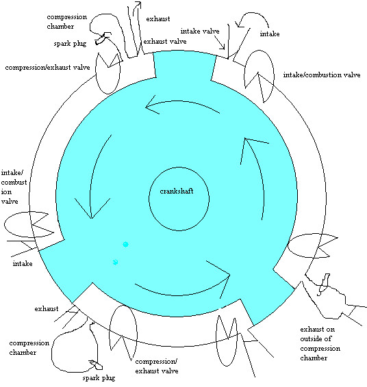
Here's how it works:
The design is that of any other four cycle engine, with intake, compression, combustion, and
exhaust phases. Placement of each of the parts could use some adjustment, this picture is just
to portray the concept. The principal behind the design is to have everything spin around
a center axis. The main spinner (attached to the crankshaft) is balanced and spins around
the crankshaft. The compression/exhaust and intake/combustion valves also spin, but around their own
axis, near the border of the piston path.
Now I realize there's a lot of complex linkage required which I haven't worked
out the details of, but I'm sure it's possible. It's just a matter of working out
the cycle and period of the valves. They are functionally the equivalent of the camshaft, except
that they ARE the valves instead of controlling the valves.
The spinning valves I realize have to have really killer bearings because they spend most of
their time taking lots of lateral pressure blasts. And of course, there's lots of sealing problems.
But I figure if mazda can make a Wankel engine not leak this should be possible as well.
The center section in blue is what spins. I have to admit I haven't worked out or have any clue
how to work out what the best setup is. I don't know how many piston sections are optimal,
how big the radius of the spinner should be, how massive the rotating valves have to be,
but I figure you could
make this pretty small, and line a bunch of them up next to each other for more power.
I'll admit, this isn't a perfectly rotary engine. The intake and exhaust valves don't spin.
You could do that if you want, but I don't think those valves would be very big and it probably
wouldn't be worth it add all the complexity of making them spin. It's not very much metal to shake around.
Intake phase:
For the intake phase, you want to create a vacuum but leave the intake valve open to get
fresh air in. So the intake/combustion valve would be in a closed position, the intake
valve would be open, exhaust valve closed, and the compression/exhaust valve would be open so the piston could pass
by it.
Compression phase:
For the compression phase, the compression/exhaust valve and the exhaust valve would be closed and
as the piston came towards it, the air would get compressed into the compression chamber.
After the leading edge of the piston seals off the entrance to the compression chamber,
you quickly spin the compression/exhaust value open so the piston doesn't smash into it.
Combustion phase:
As soon as the tail end of the piston passes the entrance to the combustion chamber you can ignite
the spark plug. The intake/combustion valve, and intake and exhaust valves will all be closed
and the piston will be thrust forward.
Exhaust phase:
After the energy of the explosion has been consumed pushing the piston, the compression/exhaust valve
is closed, the exhaust value is opened, and the next piston on the spinner comes around and pushes the
'dirty' air out the exhaust hole. As this piston passes the intake hole, the intake/combustion valve
will close and this position will be the start of the next intake phase. The exhaust valve will close
after the leading edge of the piston passes it.
7/15/04 I just had a thought today. I realized you could put the exhaust vent on the outside
of the compression chamber, so you'd get some amount of exhaust air flushing through the
compression chamber, thus doing a better job of exhausting the consumed air/gas mixture.
I made a new picture and in the bottom right corner, you can see what I mean.
It also seems that there should be a way to get the intake to flush some fresh air through the combustion
chamber so there's even less remaining exhaust.
One thing that doesn't come out in the picture very well is that the compression chamber isn't very big,
it's just a place to put the compressed air while the piston passes it. Similar to the compression
area of a Wankel engine, it's just a small cutout where the air can seep by to get to the next chamber.
Problems that I've thought of so far:
If the timing belt or chain in a typical Otto engine breaks and you don't have enough clearance between
the piston and the valves, you end up smashing the pistons into the valves and need a valve job.
If some of the linkage controlling the rotating valves in this engine were to break, well... I'll
leave the results up to the imagination of the reader. It won't be pretty though.
The sealing problems would be interesting, because you'd have to seal the c-shaped circle around
the piston (I'm assuming a circle is a good shape, maybe a rectangle would be better)
and the sides of main spinner. The piston could be a lot shorter than I've drawn it though.
Also since the spinner is so massive (relatively speaking to other engines) there might be
some gyroscopic-forces problems. But nowhere near as bad as a turbine engine. This thing won't
be spinning all that fast.
I realize the location and positioning of some of the parts (like the compression chamber) aren't
great or even pretty, but again, this picture is just to express the idea. This picture is already
the product of many design revisions. Undoubtedly there are many more to be made. The Otto engine is
over 100 years old. My engine is about 9 months old.
you can email me at spamme@deadpelican.com